Eddy current generation in a metallic conductor

A.1 General
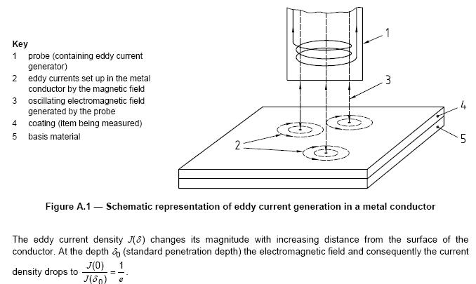
Eddy current instruments work on the principle that a high frequency electromagnetic field generated by the probe system of the instrument will produce eddy currents in an electrical conductor on which the probe is placed. These currents result in a change of the amplitude and/or the phase of the probe coil impedance, which can be used as a measure of the thickness of the coating on the conductor (see Example 1) or of the conductor itself (see Example 2).
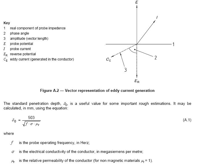
Figure A.1 represents eddy current generation in a metal conductor and Figure A.2 is a vector representation
of eddy current generation.


The amplitude-sensitive eddy current method is best suited to the measurement of non-conductive coatings on non-magnetic basis metals (see Example 1) but also to bare non-magnetic metallic coatings on nonconductive basis materials (see Example 2). The phase-sensitive eddy current method (see ISO 21968) is best suited to the measurement of non-magnetic metallic coatings on metallic or non-metallic basis materials (see Example 2) especially if the metallic coating has to be measured through paint or a contactless measurement is necessary, i.e. a “Lift-off” compensation is necessary.
A.2 Example 1 — Non-conductive coating on a conductive basis material
In this case the eddy current density is only determined by the distance between the probe and the basis metal, i.e. the coating thickness. In order to achieve this the base material is thicker than the minimum basis material thickness. This minimum thickness, dmin, in mm, can be estimated as (see 5.3.): dmin = 2,5 δ0 (A.2)
If the basis material thickness is lower than this minimum thickness, dmin, the measured value of the coating thickness will be affected.
A.3 Example 2 — Conductive coating on a non-conductive basis material
In this case the eddy current density is determined only by the thickness of the conductive coating. The approximate maximum measurable thickness, dmax, in mm, may be calculated from the equation:
dmax = 0,8 δ0 (A.3) i.e. the thickness range is limited by the penetration depth δ0 and if the conductive coating thickness is further increased, it will have no further influence on the generated eddy currents.
NOTE dmax is sometimes called “saturation thickness”.

Comments are Closed